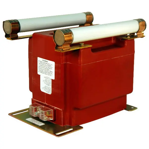
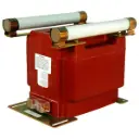
Medium Voltage Indoor Potential Transformer
Models PTG5-1-110 & PTG5-2-110
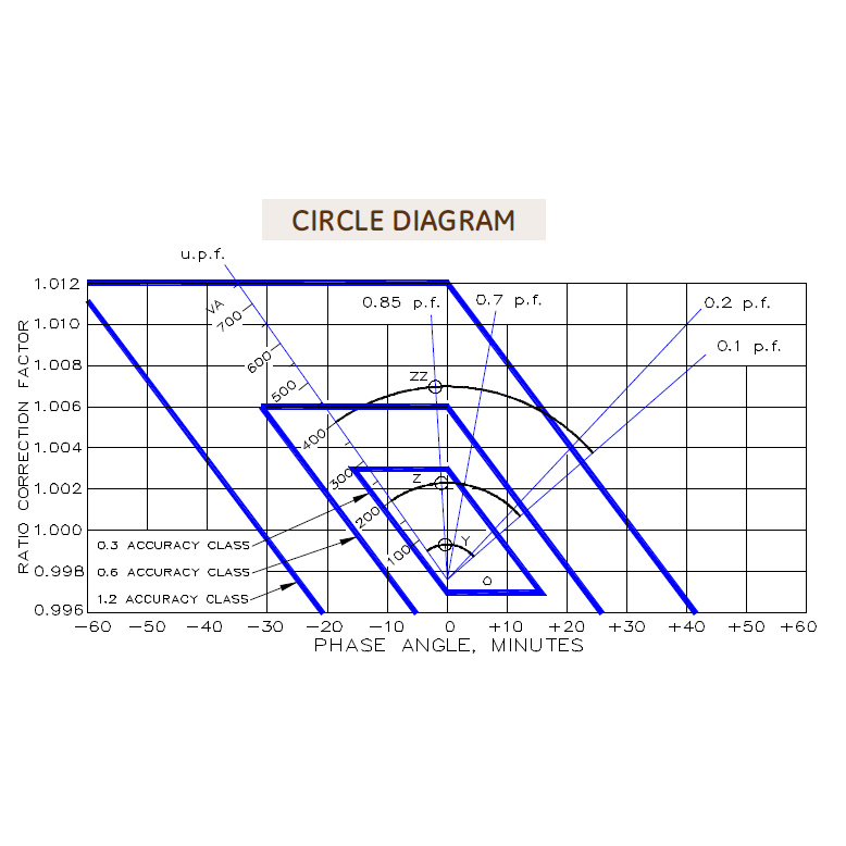
- ACCURACY CLASS:
- 0.3 WXMY, 1.2 ZZ at 100% rated voltage with 120V based ANSI burden.
- 0.3 WXMY, 1.2 Z at 58% rated voltage with 69.3V based ANSI burden.
- FREQUENCY: 60 Hz
- MAXIMUM SYSTEM VOLTAGE: 5.6kV BIL 60kV
- Thermal rating:
- 1500 VA 30°C amb.
- 1000 VA 55°c amb.
- Approximate weight: 85 lbs. unfused
- Hardware
- Primary terminals that are unfused are 1/4-20 brass screws with one flatwasher and lockwasher.
- Primary terminals that are fused are 1/4-20 brass screws with one flatwasher and lockwasher and two nuts.
- Secondary terminals are No. 10-32 brass screws with one flatwasher and lockwasher.
- The core and coil assembly is vacuum encapsulated in polyurethane resin.
- Thermal burden rating is for 120 volt secondaries.
- Plated steel mounting base.
- Switchgear style ("SS" or "S" suffix) is similar to fused style. No fuse or fuse clip is provide, but inserts for fuse clips are supplied.
- A test card is provided with each unit.
Fuses
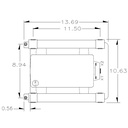
- Physical Specifications (Except as noted in (d) below)
- Caps Diameter: 1.63"
- Clips on Center: 11.5"
- Fuse Length: 13"
- Voltage Rating: 15.5kV
- Interrupting Amperes (SYM): 80,000
- Suggested Rating, Continuous Amperes. (Higher rating may be used at users option to avoid unusual clearing due to conditions resulting from magnetizing in-rush.) Note: It is recommended that system line-to-line voltage not exceed the transformer maximum system voltage level.
- 7200/120V: 1.0E
- 4800/100V: 1.0E
- 11000/120V: 0.5E
- 12000/120V: 0.5E
- 13200/120V: 0.5E
- 14200:120V: 0.5E
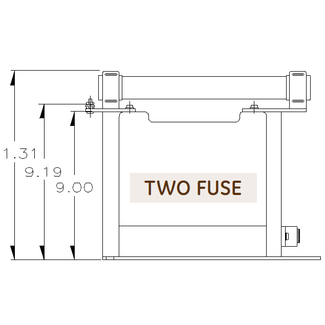
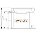
Notes: Two Bushing PTG5-2 Group 1 or 2
(a) Two fuse transformers should not be used for Y connections. It is preferred practice to connect one lead from each voltage transformer directly to the neutral terminal, using a fuse in the line side of the primary only. By using this connection a transformer can never be made “live” from the line side by reason of a blown fuse in the neutral side. For continuous operation the transformer primary voltage should not exceed 110% of rated value.
Notes: One Bushing PTG5-1, Group 4A or 4B
(b) Voltage transformers connected line-to-ground cannot be considered to be grounding transformers and must NOT be operated with the secondaries in closed delta because excessive currents may flow in the delta.
(c) Most voltage transformers are lightly loaded, particularly when associated with watthour metering and relaying schemes. If the voltage transformer has one primary lead grounded, and during an abnormal condition creating a large overvoltage, the transformer may saturate, and its impedance may cause ae a resonance with the system capacitance. This resonance, or oscillation, may be sustained and could destroy the voltage transformer. If, however, the secondaries are connected in delta, with a broken corner, and a suitable power resistor is connected across the broken corner, then ferroresonance can be damped. Our recommendation for the resistive value is shown on the catalog sheet where it applies. The power rating is determined by the user.
- PTG5-1, Group 4A or 4B damping resistor value: 65 Ω
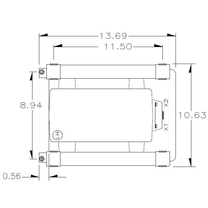
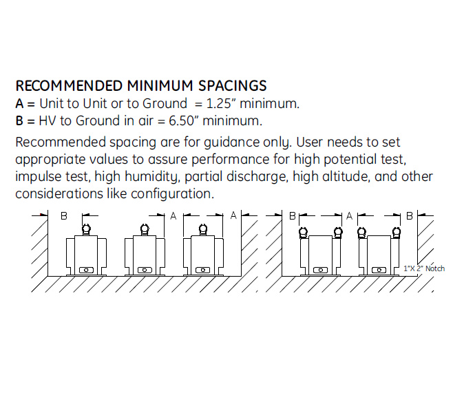
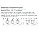
RECOMMENDED MINIMUM SPACINGS
Unit to Unit or to Ground = 0.75” minimum.
HV to Ground in air = 3.00” minimum.
Recommended spacing are for guidance only. User needs to set appropriate values to assure performance for high potential test, impulse test, high humidity, partial discharge, high altitude, and other considerations like configuration.
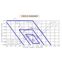
Circle Diagram
Specifications
| Product | |
|---|---|
| Brand | Instrument Transformers Inc |
| Model | PTG5 |
| Input Frequency | 60Hz |
| Input Range | 13.2kVAC |
| Output | 120VAC |
| ECCN | EAR99 |
| Tariff Code | 8504.31.4065 |
| Accuracy | 0.3 W, 0.3 X, 0.3 M, 0.3 Y, 0.3 Z, 1.2 ZZ |
| Insulation Level | 15.5kV, 110kV BIL full wave |
| Potential Transformers | |
|---|---|
| PT/VT Turns Ratio | 110/1 |
| PT/VT Thermal Rating | 1.5kVA at 30°C amb., 1.0kVA at 55°C amb. |
| PT/VT Group | Group 2. Rated Voltage: 100% L-L, 58% L-N |
| PT/VT Rec. Primary Fuse Rating | 0.5E |