


Application
- Protection of three phase electrical equipment sensitive to damage due to loss of phase, phase unbalance or improper phase sequence.
Ambient Temperature Range
- Operation: -30°C to + 60°C
- Storage: -55°C to +85°C
Input Voltages
- Nominal: 120V
- Rating: 90V - 125V
Frequency
- 50/60 Hz.
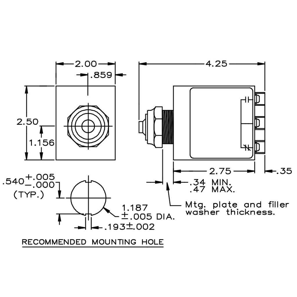
Terminal screws are #6-32 nickel plated brass.
Shipping weight 0.6 lbs.
Specifications:
- Failsafe: Trip free contacts will not operate if a fault is present.
- Automatic reset. (Configurable to manual reset, See applications notes.)
- Fixed undervoltage trip point: approx. 90% pick up, 80% dropout.
- Operates at 6% phase unbalance.
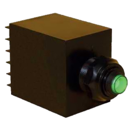
- Operates green LED indicator.
- Isolated Form “ C ” output contacts.
- Output contact rating: 250 V ac, 5 Amps, (general use).
- 3 second drop-out delay to avoid nuisance tripping
Applications Notes
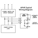
If the power conditions are normal, 3 seconds after power is supplied to the APVR the contacts will transfer, permitting operation. In normal applications, this power will already be applied to the APVR and there is no time delay in operating.
The correct phase sequence must be established upon initial installation for proper operation of the relay. Any subsequent change in phase will cause the relay to trip. If the relay is re-energized and the phase sequence is incorrect the relay will not operate.
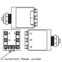
The device is shipped from the factory in the automatic reset mode with a jumper on terminals 6 & 7. Operation can be changed from automatic reset to manual reset by removing the external jumper. Automatic reset means that upon fault removal the device reset automatically to perform is mounting function. For manual reset simply remove the jumper and connect a normally open pushbutton across terminals 6 and 7.
Upon application of power the green LED indicator will illuminate. If a fault exists the green LED will remain illuminated for these three seconds and then go out. This is normal and indicates that line power is present but a fault condition has been detected. The output contacts will remain in their de-energized failsafe state.
If no fault exists upon application of power the green LED indicator illuminates and three seconds later the relay contacts transfer. Upon detection of a fault, the green indicator light will go out and three seconds later the relay contacts revert to their de-energized state. This three second delay prevents nuisance tripping of the APVR.
In service the line voltage to the device may be interrupted on various occasions. In the automatic reset mode the device will resume its monitoring function approximately three seconds after power is restored. In the manual reset mode the reset pushbutton must be pressed.
“Failsafe” operation is achieved by the following features:
- The relay is energized and the output contacts are transferred under “ normal ” conditions only.
- Should the output relay itself fail or in the event of internal circuit failure, the relay will revert to the de-energized position
Unbalance Calculation
Max. deviation from average / Average x 100 = % Unbalance
Example:
- Nominal Voltage = 120V
- ØA - ØB = 120V
- ØB - ØC = 110V
- ØC - ØA = 107.5V
- Average = (120 + 110 + 107.5) / 3 = 112.5V
- Nominal Voltage - Average = Max. deviation from average
- Max. deviation from average = 120 - 112.5 = 7.5V
- % Unbalance = 7.5 / 112.5 x 100 = 6.67%
Specifications
| Brand | Instrument Transformers Inc |
| Model | APVR |
| Input Range | 3P 120VAC |
| Input Frequency | 50Hz, 60Hz |
| Tariff Code | 8536.41.0050 |
| ECCN | EAR99 |